
Section 03 10 00Resources › Division 03 Projects
Project Control: projects across several drawings
Project Control holds one tiling that every discipline inherits, so demolition, existing conditions, grading and layout all sit on the same sheet boundaries, authored once in a control drawing. It creates each discipline's drawings, splits a discipline across files at a count you choose, numbers straight through, and keeps one sheet set for the project.
Project Control
Project Control works at project scale instead of one drawing at a time. You author the tiling once in a control drawing, and the output drawings are created and maintained from it.
It is not only for multi-discipline work. There are three uses, and they combine:
- Disciplines. Several disciplines, such as existing conditions, demolition plan, layouts or grading, inherit the same sheets, each with its own prefix and numbering.
- Layout count. One discipline split across several drawings, so no single file carries more layouts than you want it to, with every file kept in sync.
- Both. Disciplines and layout count controlled together.
The flow: author the tiles in the control drawing, press Assign Disciplines to set prefixes and numbering, then Build Set or Update to create the output drawings, their sheets, the sheet set and the index.
Project Control is not Key Plans. Key Plans coordinates drawings that already exist, producing an index or cover layout and project-wide key maps. Project Control authors the tiling and creates the drawings from it.
Using more than one Project Control
A project can have as many control drawings as you want. There is no limit, and no reason to keep it to one.
Reach for another one whenever it suits the work: several scales across the project, breaking a large set into separate files, coordinating disciplines, or all of those at once. The principle behind it stays the same: every bundle of disciplines that shares the same tiles shares one Project Control.
One common reason is mixing Single VP and Multi VP work. A control drawing is one or the other: Single VP controls one viewport per layout, Multi VP controls two or more, and that difference decides which sheets are eligible for which control. So a project with both uses a control drawing of each, plan sheets under one, and Plan and Plan or Plan and Profile under the other.
The one rule is the sheet set. Point every control drawing at the same one and the whole project stays connected in Sheet Set Manager, however many places the tiling is authored in.
Set up a Project Control drawing
A control drawing is where the project's tiling is authored. It is preview only: tile labels stay blank until numbering is assigned, and sheets are never built here. Sheets are built in the discipline drawings by Build Set or Update.
Step 1. Save the drawing first. The project file lives next to the control drawing, so it needs a real location on disk.
Step 2. Press Project Control on the Welcome tab and choose Single VP or Multi VP for the whole project.
Step 3. Author the tiling as you would in any drawing: Set TB, Primary VP, Create Preview, and Add Tile for extras.
Assign Disciplines comes next, and gives the project its names and numbers.
Assign Disciplines
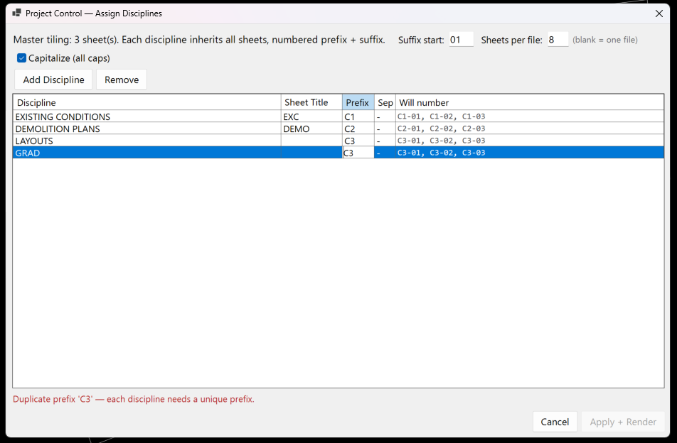
Assign Disciplines is where the project gets its file structure, its names and its numbers. The header tells you how many sheets the master tiling holds; every discipline inherits all of them.
Step 1. Set how many sheets go in each file. This is your choice and it decides how the project breaks into drawings. Leave it blank to keep each discipline in a single file. The count is by sheet, so a sheet carrying two viewports still counts as one.
Step 2. Set the suffix start, once, for the whole project. 01 gives C1-01, 101 gives C1-101.
Step 3. Add a row per discipline: its name, a sheet title, a unique prefix such as C1, C2 or C3, and a separator. A blank sheet title falls back to the discipline name.
Every prefix has to be unique. Reuse one and the row is flagged and the build button stays disabled until you fix it, rather than letting two disciplines collide in the numbering.
The Will number column previews the result as you type, so you see C1-01, C1-02, C1-03 before committing to it. There is also a capitalize option if your standard wants discipline names in all caps.
Step 4. Press Apply and Render.
Afterwards the tiles show their project numbers and each file group takes its own colour. To renumber from a given point, retype a number on a tile and run Assign Disciplines again.
Adding or removing a discipline
The discipline list can change during a project. Both changes start in Assign Disciplines, in the control drawing.
To add one, press Add Discipline, fill in its name, sheet title and a unique prefix, apply, then run Build Set or Update. The new discipline inherits every tile in the project and the key map settings already chosen.
To remove one, select its row, press Remove, apply, then run Build Set or Update. Its drawings retire to the backup folder you nominated rather than being deleted, its sheets leave the sheet set, and its subset is removed from the sheet set once it is empty.
Define Regions
Regions split the project's output files geographically, before size is considered.
Step 1. Press Define Regions.
Step 2. Add each region by selecting a closed polyline, drawing a rectangle, or choosing Alignment to get one region per alignment. With Alignment nothing is drawn: the alignment itself is the boundary, and sheets never mix across alignments.
Step 3. Press Done. The summary lists the regions, and they take effect at the next Assign Disciplines, where files break by region first and by Sheets per file second.
If a sheet sits between two regions, Assign Disciplines asks which one it belongs to.
Build Set or Update
Build Set or Update creates and maintains every output drawing in the project.
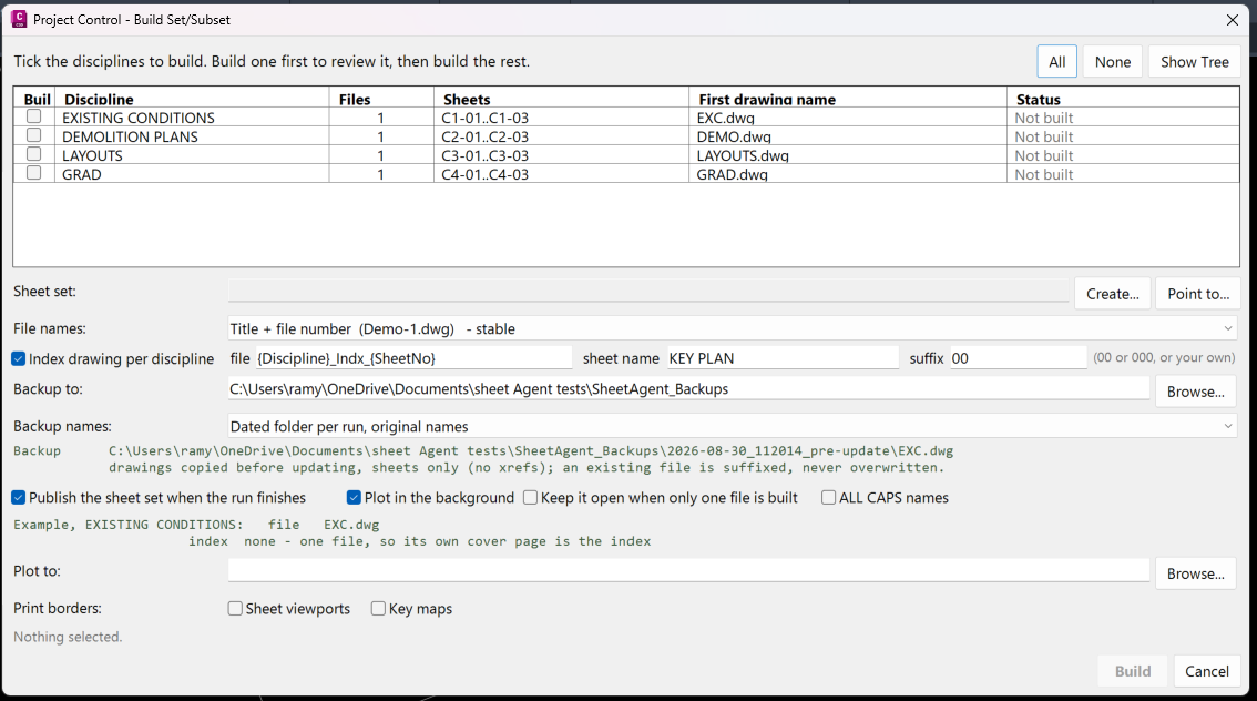
Step 1. Tick the disciplines to build. The table shows what each will produce before you run it: how many files, which sheet numbers, the first drawing name, and whether it is built, needs updating, or has not been built yet. Building one first and reviewing it before running the rest is worth the extra minute.
Step 2. Point at a sheet set, or create one. Every discipline enrols in the same one.
Step 3. Choose the file naming pattern for the drawings and for the index. The index is always a standalone drawing, with its own file pattern, sheet name and suffix.
Step 4. Set the backup location and how backups are named. Drawings are copied before updating, sheets only and no XREFs. An existing backup is suffixed rather than overwritten, so a run can never destroy an earlier one.
Step 5. Choose what happens at the end of the run: publish the sheet set, plot in the background, and whether to leave the drawing open when only one file was built. Set the plot destination if you are plotting, and tick print borders for sheet viewports or key maps if you want them.
Step 6. Press Build.
Run it again whenever the project changes. It updates in place, and the table reports where every file stands.
Changing the project later
Every project change starts in the control drawing.
Step 1. Change the tiling there: retile, move or delete tiles, or retype a sheet number.
Step 2. Run Assign Disciplines if the numbering needs re-approving, then Build Set or Update. Every discipline follows the new state.
Two rules keep a project stable through this. Sheets renumber but files never rename, so file names and the links into them stay put. A deleted sheet is removed rather than held open as a numbered gap.
If every sheet in a file is removed, that drawing retires: it moves to the backup folder you nominated. Nothing is deleted.
Working in a managed discipline drawing
A discipline drawing belongs to the project, so the project-level controls defer to the control drawing. Set TB, Primary VP, Retile, Renumber and sheet names all report that they are managed by Project Control and point you back there. That is one source of truth, not a lock-out.
Everything else on those sheets is yours. Add your own viewports, annotations, support viewports and secondary viewports freely. Project updates never touch what you added; only what SheetAgent for Civil 3D created is maintained.
Secondary VP
A secondary viewport gives one sheet its own extra view: a section, a detail, or a manually drawn profile. There is one tile per sheet, so every sheet can show something different.
Step 1. Press Set Secondary VP and define its area on the title block layout, exactly as with Primary VP.
Step 2. Press Preview Secondary VP and click a centre in model space for each sheet. Enter skips a sheet, Escape stops. That first click is only a starting point: each tile can then be moved, rotated or even stretched into position in model space, and the update reflects that tile on its own layout.
Step 3. Press Update Sheets to turn every placed tile into that sheet's second viewport.
A secondary viewport is not a support viewport. A support viewport is the legend case: one shared tile repeating the same content on every sheet. A secondary viewport is one tile per sheet, so each sheet shows its own.
At each Update Sheets the viewport follows its tile, scaling that sheet's view so the whole tile fits the window. No north arrow is placed in a secondary viewport, and it behaves the same in a regular drawing and in a project discipline.
Layer control across a whole discipline
In a managed project a discipline's layouts are often spread across several drawings. Layer control follows the discipline rather than the file, so you set it once and it reaches every drawing in that family.
Step 1. In any drawing of the discipline, say C2-01, set the layers inside one viewport the way you want them.
Step 2. Press the button for that viewport type, Apply Layers Viewport, Apply Layers Keymaps or Apply Layers Profile, and pick the viewport as the source.
Step 3. Choose the scope. In a managed drawing all three of those buttons offer the same choice: this drawing only, which behaves exactly as it does anywhere else, or across the discipline, which pushes the state to every drawing in that family.
The other drawings are updated offline. They are not opened, so the pass is quick and nothing is left waiting on your screen.
Model space layers have their own button. Apply Layer Model Space appears only in a drawing managed by Project Control, and pushes model space layer settings across the discipline the same way, without opening the files.
Index and cover drawings are skipped. They are almost always laid out differently from the sheets, so applying a sheet's layer state to them would be wrong more often than right.
Xrefs for a whole discipline
A discipline's drawings usually need more references than the light background the control drawing carries. Discipline Xrefs keeps lists for each discipline, one for its layout files and one for its index drawing, and adds them to the drawings that discipline has built, without opening them.
Step 1. In the control drawing, press Discipline Xrefs in the Project Control section. It stays greyed until the first discipline has been built.
Step 2. Pick the discipline. It has two lists: one for the layout files, which every built layout drawing of the discipline gets, and one for the index drawing, which can take a different set.
Step 3. Fill each list with Add, and set Attach / Overlay, Layer and Lock / Unlock per row, the same list as Batch Xrefs.
Step 4. Press Save & Apply. The lists are saved and applied together: every discipline with a list gets its references added to its built drawings.
The drawings must be closed. If any of them is open, the run stops before changing anything and reports it.
Discipline Xrefs works on its own, apart from Build Set or Update: a build never adds or removes these references. If a drawing is rebuilt, press Save & Apply again to put them back. References already present are skipped, so applying twice changes nothing, and references you attached yourself are never touched.
Profile Split Sync Required
A Profile Split Sync Required message means the tiling has changed, so the split profile views in the source drawing no longer line up with the sheets. They have to be re-cut at the source before the profile viewports match again.
The direct route is Assign to SheetAgent. Your drawing saves itself, the source is opened and the splits re-cut, then it returns and finishes the sync with no clicks in between.
To do it yourself, press Do it manually, run the profile split in the source drawing, then update here.
End of section 03 10 00
Something here not matching what you see? Tell us and we will fix it. Back to Resources, or the FAQ.