
Section 02 30 00Resources › Division 02 Sheets
Multi VP: plan and profile sheets
Multi VP puts two or more viewports on one sheet. Plan and Profile pairs a plan with its profile view along an alignment. Plan/Plan stacks two different tiles on one sheet, which suits narrow corridors like utility runs. Plan Duplicate shows the same tile twice with different layer states, for existing against proposed.
Before you start. To use alignments, make sure the alignments you plan to use are data-shortcut referenced into the drawing first.
Multi VP: start to finish
Step 1. Choose Multi VP on the Welcome tab. The palette switches to the Multi VP tab.
Step 2. Set the title block and the viewport size. This comes before every placement mode, without exception. See Title blocks, north arrows and scale bars.
Step 3. Press one preview mode button: Plan/Plan, Plan and Profile, or Plan Duplicate. Plan/Plan and Plan Duplicate take a viewport count and an arrangement in their setup dialog. Plan and Profile is always one plan viewport plus one profile viewport per sheet.
Step 4. Adjust the preview tiles in model space if anything needs moving.
Step 5. Press Build Sheets. This is first time only, and it enables once a preview exists.
Step 6. After any tile change, press Update Sheets. It is incremental, so unchanged tiles are skipped. There is no rebuild step; Update handles everything after the first build.
Plan/Plan sheets
Plan/Plan puts two or more different tiles on one sheet, running in series. It is the opposite of Plan Duplicate, which puts the same tile in two viewports.
It earns its place on narrow work. A utility run or a roadway layout is a thin strip, so one viewport per sheet leaves most of the sheet empty and stretches the set out over far more sheets than it needs. Stacking two, or up to six, consecutive tiles on one sheet covers much more length per sheet without dropping the scale.
Step 1. Set the title block and the viewport size. This comes before every placement mode, without exception. See Title blocks, north arrows and scale bars.
Step 2. Press Plan/Plan. A pattern picker asks how the tiles should be placed: Path, Alignment or Free.
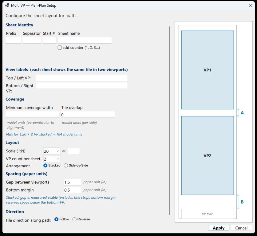
Step 3. The setup dialog opens.
- Sheet identity: prefix, separator, start number and sheet name, with an option to add a counter.
- View labels: a name for each viewport. These become the per-sheet viewport titles.
- Coverage: the minimum width each sheet takes in, and the tile overlap. The dialog works out the maximum that will fit at your scale and arrangement and tells you what it is, which matters here because the whole point is fitting more in.
- Layout: the scale, how many viewports go on a sheet, and whether they stack or sit side by side. Side by side suits a run that is wide and short; stacked suits the narrow strip this mode is for.
- Spacing, in paper units: the gap between viewports and the bottom margin. Stacked, the gap is the visible gap and includes the title strip.
- Direction: whether tiles run with the path or against it.
Step 4. Press Apply, check the preview tiles in model space, then press Build Sheets.
The viewport count is yours to set, from two up to six.
Plan and Profile setup
Plan and Profile needs two things in the drawing: a Civil 3D alignment, and a profile view for it. The profile view is looked for in the current drawing and in its XREFs, so it can live in a referenced drawing.
Step 1. Set the title block and the viewport size. This comes before every placement mode, without exception. See Title blocks, north arrows and scale bars.
Step 2. Press Plan and Profile, then pick the alignment. Cyan letters mark each alignment in model space so they are easy to tell apart.
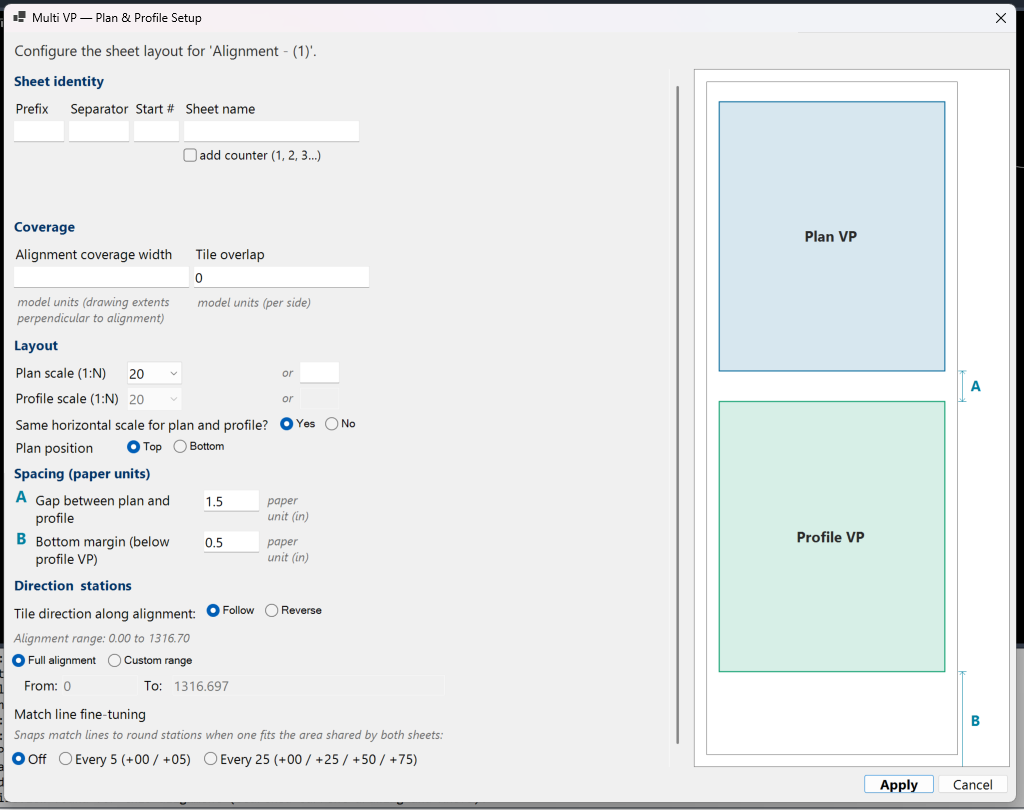
Step 3. The setup dialog opens, in five parts.
- Sheet identity: prefix, separator, start number and sheet name, with an option to add a counter so repeated names read 1, 2, 3.
- Coverage: how wide a band either side of the alignment each sheet takes in, and how much neighbouring tiles overlap. Both are in model units, and the overlap is per side.
- Layout: a plan scale and a profile scale, each a preset from the dropdown or a value you type. Answer whether the two share the same horizontal scale, and whether the plan sits above or below the profile.
- Spacing, in paper units: the gap between the plan and the profile, and the bottom margin below the profile viewport. The preview on the right marks both, so you can see what you are setting.
- Direction and stations: whether tiles run with the alignment or against it, and whether to cover the full alignment or a station range you type. The alignment's own range is shown above the field.
Match line fine-tuning sits at the bottom of the same dialog. See Where the match lines land.
Step 4. Press Apply and check the preview tiles in model space. Move or adjust any of them now. Each sheet gets one plan viewport and one profile viewport.
Step 5. Press Build Sheets. Station labels are computed from the alignment and clamped to its bounds.
Build Sheets greys out after the first build. Update Sheets handles every change from then on, and Add Tile fills coverage gaps.
Plan Duplicate sheets
Plan Duplicate puts two viewports on a sheet showing the same area, which is the point: each viewport carries its own layer state, so one sheet can show existing against proposed. For two different areas on one sheet, in series, see Plan/Plan.
Step 1. Set the title block and the viewport size. This comes before every placement mode, without exception.
Step 2. Press Plan Duplicate. A pattern picker asks how the tiles should be placed: Path, Alignment or Free.
Step 3. The setup dialog opens. Its title reads Plan-Plan Setup, because Plan and Plan and Plan Duplicate share it. The fields are the same, and they are shown on the Plan/Plan topic.
- Sheet identity: prefix, separator, start number and sheet name, with an option to add a counter.
- View labels: a name for each of the two viewports, top or left and bottom or right. These become the per-sheet viewport titles.
- Coverage: the minimum width each sheet takes in, and the tile overlap. The dialog works out the maximum that will fit at your scale and arrangement, and tells you what it is, so you are not guessing.
- Layout: the scale, how many viewports go on a sheet, and whether they stack or sit side by side.
- Spacing, in paper units: the gap between the viewports and the bottom margin. Stacked, the gap is the visible gap and includes the title strip, and the bottom margin reserves space below the lower viewport.
- Direction: whether tiles run with the path or against it.
Step 4. Press Apply, check the preview tiles, then press Build Sheets.
Then set the layer freeze and thaw inside one viewport the way you want it, and copy that state to every other sheet. See Copying layer states across sheets.
Plan VP Label edits the per-sheet viewport titles afterwards, and Layout Adjustment changes spacing without a rebuild. To extend coverage, Add Tile followed by Update Sheets.
View and profile labels
Three tools cover the labels, and they do different jobs.
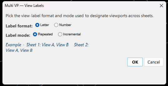
View Label sets the view designation itself: letters or numbers, and whether they repeat on every sheet or run on across the set. The dialog shows an example of what your choice produces.
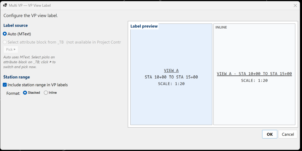
Plan VP Label configures the plan viewport label. It can be drawn as text, or taken from an attribute block in your own title block, which is the route to a company-standard label. You can include the station range and set it stacked under the title or inline beside it. In Plan Duplicate mode it also edits the per-viewport titles.
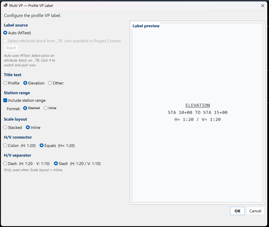
Profile VP Label does the same for profile viewports and offers more, because there is more to say. The title can read Profile, Elevation, or wording of your own. The station range can be included and stacked or inline. The scales can be stacked or inline, joined with a colon or an equals sign, and separated by a dash or a slash. A preview shows the result as you change it.
One limitation worth knowing: taking the label from an attribute block is not available under Project Control. There the labels are drawn as text.
The labels are dimension-aware. Titles centre on the actual viewport width, and Update Sheets recomputes their positions from the live viewport geometry, so narrow or resized viewports do not leave labels adrift.
To copy your Civil 3D profile labels, such as station elevation or pipe profile labels, from each main profile view onto its split profile views, open the source drawing, go to the Profile Split tab and press Sync Profile Labels. It keeps your drag positions and leaders, runs across all alignments, and asks nothing.
Customising the Multi VP template
_TEMPLATE_TB is the master template for Multi VP too. Every sheet copies its decorations and its viewport slots from it, so customise it before building where you can.
The viewport slot rectangles and their labels are drawn on the template on a cyan, non-plotting layer. Adjust those slot positions before pressing Build Sheets: both Build and Update read the slot layout from the template.
Moving the north arrow, scale bar or key map label on the template after building is fine. The new position flows to every built sheet at the next Update Sheets, and Health flags it as template position drift in the meantime.
Support viewports defined on the template flow to every sheet as well. Press Refresh Support VP to push template changes out without a full rebuild.
On multi-alignment Plan and Profile, only the first alignment owns the template dimensions. The other alignments store their own viewport heights and scale, so editing one alignment's tile heights never shifts the others.
Rotating a sheet by hand
A sheet's coverage can be rotated by hand, and the sheet follows.
Step 1. In model space, rotate the tile to the angle you want.
Step 2. Press Update Sheets.
The viewport view, the north arrow and the match lines all re-orient to match. This works in every mode, through a full 360 degrees, and on built and adopted drawings alike.
Rotate the model-space tile, not the paper-space viewport. The tile drives the result here as it does everywhere else.
What Layout Adjustment can change
Layout Adjustment changes the paper-space spacing on built sheets without a full rebuild. It is deliberately limited in scope.
It supports the stacked arrangement only. On side-by-side sheets it refuses, and a sizing change there goes through Retile instead.
The fields you get depend on the build type. Plan and Profile gives top buffer, bottom buffer, gap between viewports, and bottom margin. Plan/Plan and Plan Duplicate give gap and bottom margin only, since there is no separate profile viewport.
It runs for Plan and Profile, Plan/Plan and Plan Duplicate builds. Other build types are not supported.
End of section 02 30 00
Something here not matching what you see? Tell us and we will fix it. Back to Resources, or the FAQ.