
Section 02 10 00Resources › Division 02 Sheets
Plan sheets: array, path, alignment and free placement
Plan sheets are built from tiles you place in model space, one tile per sheet. There are four ways to place them: array fills a boundary with a grid, path follows a polyline, alignment follows a Civil 3D alignment and its stationing, and free placement drops single tiles where you click. Every mode starts from the same title block and viewport setup.
Before you start. To use alignments, make sure the alignments you plan to use are data-shortcut referenced into the drawing first.
Array placement
Array needs a boundary, and the engine fills that area with tiles.
Step 1. Set the title block and the viewport size. This comes before every placement mode, without exception. See Title blocks, north arrows and scale bars.
Step 2. Press Create Preview on the Single VP tab, choose Array, and give it the boundary to fill.
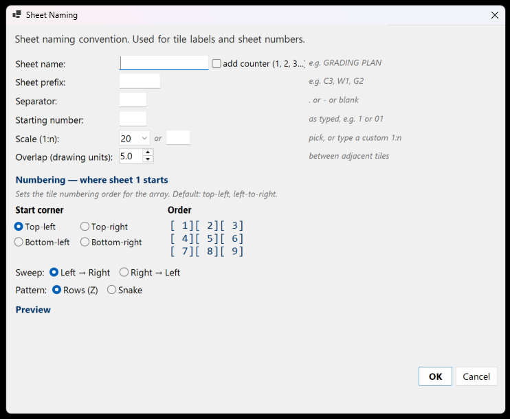
Step 3. The Sheet Naming dialog opens. It is the same dialog in every placement mode, showing only the sections that mode needs.
- Naming: sheet name, with an option to add a counter so repeated names read 1, 2, 3; sheet prefix such as C3 or W1; separator, a dot, a dash or nothing; and the starting number, taken exactly as you type it, so 01 and 1 give different results.
- Scale: a preset from the dropdown, or a custom ratio you type.
- Overlap: how much adjacent tiles overlap, in drawing units.
- Numbering: where sheet 1 starts and how the numbers run from there. Pick the start corner, whether the sweep runs left to right or right to left, and whether the pattern steps in rows or snakes back on itself. A grid beside the options shows the resulting order, so you can see 1, 2, 3 across the top before committing. The default is top left, left to right.
Step 4. Press OK. The preview is complete.
Step 5. If you are happy with it, press Build Sheets. If not, move, add, delete or rotate tiles first, and build when it looks right.
Free placement
Free places tiles by clicking, and has two modes. Single places one tile, which suits an addition or an exhibit. Multiple keeps placing, each click dropping a tile centred on the point you pick.
Step 1. Set the title block and the viewport size. This comes before every placement mode, without exception. See Title blocks, north arrows and scale bars.
Step 2. Press Create Preview on the Single VP tab, choose Free, then Single or Multiple.
Step 3. The Sheet Naming dialog opens, showing only the sections Free needs: the naming, the scale, and the tile overlap. There is no numbering order to set, because you decide it by where you click.
- Naming: sheet name, with an option to add a counter so repeated names read 1, 2, 3; sheet prefix such as C3 or W1; separator, a dot, a dash or nothing; and the starting number, taken exactly as you type it, so 01 and 1 give different results.
- Scale: a preset from the dropdown, or a custom ratio you type.
- Overlap: how much adjacent tiles overlap, in drawing units.
Step 4. Press OK, then click a centre in model space for each tile you want.
Step 5. Press Build Sheets once the tiles look right. Move, rotate, add or delete them first if they do not.
Tiles can be moved or rotated at preview or after the sheets are built, and the update carries the change through.

Path placement: sheets along a polyline
Path runs sheets along a polyline, which suits exhibits, corridors and studies where there is no alignment to follow.
Step 1. Set the title block and the viewport size. This comes before every placement mode, without exception. See Title blocks, north arrows and scale bars.
Step 2. Draw a polyline in model space along the route you want sheeted.
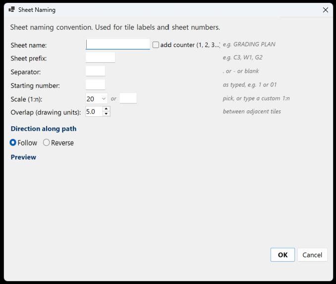
Step 3. Press Create Preview, choose Path, and pick the polyline. The Sheet Naming dialog opens with the sections Path needs.
- Naming: sheet name, with an option to add a counter; sheet prefix, separator, and the starting number taken exactly as you type it.
- Scale: a preset from the dropdown, or a custom ratio.
- Overlap: how much adjacent tiles overlap, in drawing units.
- Direction along path: run with the polyline, or against it.
Step 4. Press OK. Tiles are laid one after another along the polyline. Move, rotate or resize any of them that need it.
Step 5. Press Build Sheets for one layout per tile.
Path always uses model space match lines, and the labels carry station ranges.
Alignment placement
Alignment placement lays tiles along a Civil 3D alignment, so the sheets follow the stationing.
Step 1. Set the title block and the viewport size. This comes before every placement mode, without exception. See Title blocks, north arrows and scale bars.
Step 2. Press Create Preview, choose Alignment, and pick your alignment.
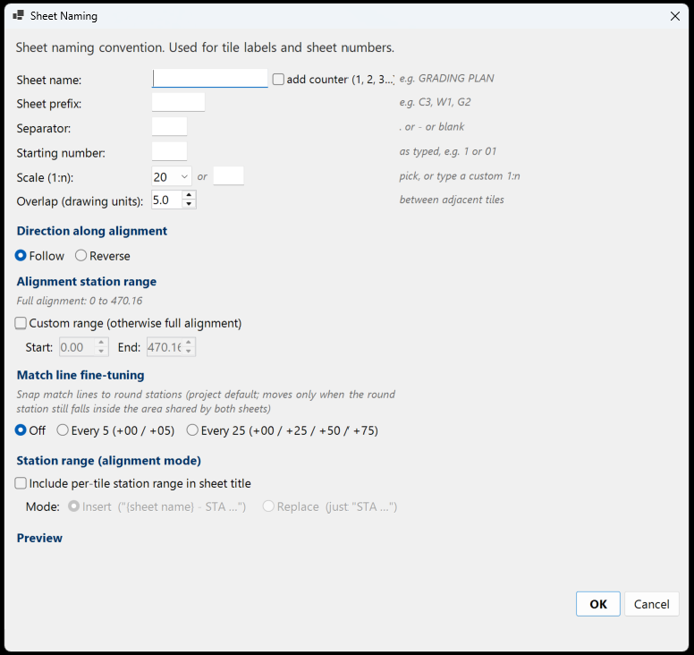
Step 3. The Sheet Naming dialog opens. It is the same dialog in every placement mode, showing only the sections that mode needs.
- Naming: sheet name, with an option to add a counter so repeated names read 1, 2, 3; sheet prefix such as C3 or W1; separator, a dot, a dash or nothing; and the starting number, taken exactly as you type it, so 01 and 1 give different results.
- Scale: a preset from the dropdown, or a custom ratio you type.
- Overlap: how much adjacent tiles overlap, in drawing units.
- Direction along alignment: follow it, or run against it.
- Station range: the full alignment by default, with its real extents shown above the field, or a custom range with your own start and end.
- Match line fine-tuning: leave the computed positions alone, or snap them to round stations. See Where the match lines land.
- Station range in the sheet title: optionally put each tile's own station range into its title. Insert keeps your sheet name and adds the stations after it; Replace uses the stations alone.
Step 4. Press OK. Tiles appear along the alignment. Move, rotate or resize any of them that need it.
Step 5. Press Build Sheets. Each tile becomes a layout with a scaled viewport, model space match lines with station labels, a key map viewport if a key map area is set, your configured support blocks, and filled title block attributes.
Build Sheets greys out after that first build. Update Sheets handles every change from then on.
If the drawing has no alignment, Path placement does the same job from a polyline.
Tiling part of an alignment
You do not have to tile a whole alignment.
Step 1. Press Create Preview and choose Alignment. Multi VP alignment setups carry the same option in their direction and stations section.
Step 2. In the sheet naming dialog, tick the custom range option and enter the start and end stations. The full alignment range is shown for reference.
Step 3. Press Build Sheets. Only that portion is tiled.
To cover the rest later, press Add Tile, which is gap-fill aware, then Update Sheets.
Why tiles cover different station ranges
With Alignment placement, tiles are generated adaptively. This is expected rather than a fault.
The physical tile size stays constant, so every sheet plots at the same size and scale.
The station range each tile covers changes with curvature: a tile covers fewer stations through a curve and more along a straight.
That is what keeps the alignment inside the viewport on every sheet.
Filling coverage gaps
Step 1. Open Health and press Gap Preview. Non-plotting markers appear in model space wherever tile coverage falls below your minimum.
Step 2. Press Add Tile. It is gap-fill aware, so it covers gaps at the start, at the end, and in the middle, and it can add tiles at a different scale or naming.
Step 3. Place or accept the new tiles over the highlighted areas.
Step 4. Press Update Sheets, not Build Sheets. Layouts are generated for the new tiles and unchanged tiles are skipped.
Press Gap Preview again to turn the markers off.
When tiles move
Move or resize the tile polylines in model space, then press Update Sheets. Changes are detected automatically: layouts, match lines and key maps update in one pass, and unchanged tiles are skipped.
Build Sheets stays greyed out once sheets exist. That is deliberate, because Build is first-time only.
If match line labels still reference old neighbours, press Update Match Lines to regenerate them from the current tile layout.
For a larger fix, Health offers Retile to regenerate the tile layout when drift is detected, and Reset Project Data to clear project data and start again.
Assigning a sector or area
Title block attributes must be configured before a sector can be written to them.
Step 1. Press Assign Sector in the Sheet Management section.
Step 2. Type the sector or area name and tick the sheets it applies to.
Step 3. The name is written into the area attribute of each selected sheet's title block and saved in the sheet records.
To adjust the area text on individual sheets later, use Edit TB Fields.
The overview cover sheet
The overview sheet is an optional zoomed-out cover sheet showing every tile, so reviewers get a single index sheet.
When you press Build Sheets, a dialog asks whether to create it and lets you set its title.
Its sheet number mirrors your numbering with the sequence zeroed out, so sheets numbered C4-01 give a C4-00 overview. Its viewport scale is calculated for you.
For a project-wide overview across several drawings, use Key Plans instead.
End of section 02 10 00
Something here not matching what you see? Tell us and we will fix it. Back to Resources, or the FAQ.